Tuesday, December 24, 2013
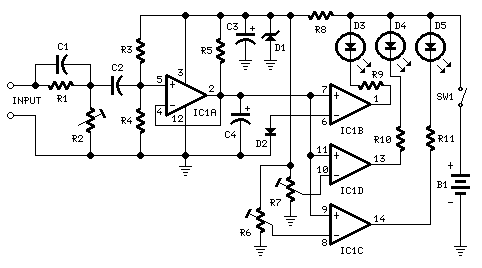
25W Three Level Audio Power Indicator
- D5 illuminates at 2W
- D4 illuminates at 12.5W
- D3 illuminates at 24.5W
 |
| 2W, 12.5W, 24.5W - Three Level Audio Power Indicator Circuit Diagram |
Parts:
- R1 100K 1/4W Resistor
- R2 50K 1/2W Trimmer Cermet
- R3 330K 1/4W Resistor
- R4 1M2 1/4W Resistor
- R5 470K 1/4W Resistor
- R6,R7 500K 1/2W Trimmers Cermet
- R8 1K5 1/4W Resistor
- R9-R11 470R 1/4W Resistors
- C1 47pF 63V Ceramic Capacitor
- C2 100nF 63V Polyester Capacitor
- C3 47µF 25V Electrolytic Capacitor
- C4 1µF 25V Electrolytic Capacitor
- D1 BZX79C5V1 5.1V 500mW Zener Diode
- D2 1N4148 75V 150mA Diode
- D3-D5 3mm. Yellow LEDs
- IC1 LM339 Quad Voltage Comparator IC
- SW1 SPST Slider Switch
- B1 9V PP3
- Clip for 9V PP3 Battery
Notes:
- The simplest way to connect this circuit to the amplifier output is to use a twisted pair cable terminated with two insulated crocodile clips.
- Setup is best accomplished with an oscilloscope or an audio millivoltmeter like the one described in these pages.
- A 1KHz sine wave generator with variable output is also required (see a suitable circuit in this website also).
- Connect the generator to the amplifier input and the Audio Power Indicator to the output of the amplifier, in parallel with the oscilloscope probe or the audio millivoltmeter input.
- When using high power outputs disconnect the loudspeakers to avoid Tweeters damage and connect in their place an 8 Ohm 20-30 Watt wirewound resistor.
- Remember that VRMS output is equal to output Peak-to-Peak Voltage divided by 2.828.
- RMS power output in Watts is equal to VRMS2 divided by speaker impedance (usually 8 or 4 Ohms).
- Example: set the output of the 1KHz sinewave generator to read 14V on the audio millivoltmeter (24.5W 8 Ohms). Set R2 until D3 illuminates, and be sure that D3 turns-off when diminishing a little the generators output.
- Do the same with R7 for D4 and R6 for D5. The readings of the audio millivoltmeter must be 10V (12.5W 8 Ohms) and 4V (2W 8 Ohms) respectively.
- Source
- Red Free Circuit Designs
Subscribe to:
Post Comments (Atom)
No comments:
Post a Comment
Note: Only a member of this blog may post a comment.