Wednesday, November 12, 2014
indicator alarm for Water level circuit with explanation
This electronic circuit is a simple water level indicator alarm that is based on few transistors . The circuit is very simple and it has a very low current consumption , so you can use a 9 volts battery to powering this water level indicator alarm . This water level indicator alarm electronic circuit can be used even for rain alarm or short circuit alarm , a resistance with a value from 0 to about 1 M ohm will trigger it . The Q1 transistor acts as a switch which applies current to the unijunction relaxation oscillator Q2 . The signal frequency of the alarm circuit is give by the values and ratios of the C1 / R2 .
If you don’t have the transistors marked on the schematic diagram you can replace them almost with any similar types . As you can see in the schematic diagram , between probes is mounted a switch ( you can use a push-button) for testing the circuit , but it can be removed .
The speaker used in this project must have a impedance between 15 and 90 ohms .

Sunday, October 5, 2014
Modular Preamplifier Switching Center
Parts:
R1,R2,R3,R4____100K 1/4W Resistors
R5_____________560R 1/4W Resistor

SW1,SW2________2 poles 4 ways Rotary Switches

J1 to J6_______RCA audio input sockets
Comments:
This module can be a necessary addition to the Modular Preamplifier Control Center when more than two sources need to be connected to the preamplifier chain.
Four high level inputs can be selected by means of SW1 and routed to the output. The output of this module must be connected by a suitable cable to one of the two inputs of the Control Center module. In this way, a total of five inputs will be available to the user of this module combination.
The Switching Control features also the so called "Double Bar", i.e. the possibility of routing to an external unit, e.g. a recorder (tape or digital) an input signal different from that reproduced at the time by the amplifier.
For example, you can listen in to a CD whereas the signal coming from a radio station through the Tuner is routed to the recorder. This selection is operated by means of SW2.
As with the other modules of this series, each electronic board can be fitted into a standard enclosure: Hammond extruded aluminum cases are well suited to host the boards of this preamp. In particular, the cases sized 16 x 10.3 x 5.3 cm or 22 x 10.3 x 5.3 cm have a very good look when stacked. See below an example of the possible arrangement of the front and rear panels of this module.
Tuesday, December 24, 2013
25W Three Level Audio Power Indicator
- D5 illuminates at 2W
- D4 illuminates at 12.5W
- D3 illuminates at 24.5W
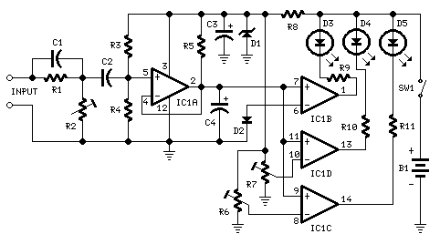 |
| 2W, 12.5W, 24.5W - Three Level Audio Power Indicator Circuit Diagram |
Parts:
- R1 100K 1/4W Resistor
- R2 50K 1/2W Trimmer Cermet
- R3 330K 1/4W Resistor
- R4 1M2 1/4W Resistor
- R5 470K 1/4W Resistor
- R6,R7 500K 1/2W Trimmers Cermet
- R8 1K5 1/4W Resistor
- R9-R11 470R 1/4W Resistors
- C1 47pF 63V Ceramic Capacitor
- C2 100nF 63V Polyester Capacitor
- C3 47µF 25V Electrolytic Capacitor
- C4 1µF 25V Electrolytic Capacitor
- D1 BZX79C5V1 5.1V 500mW Zener Diode
- D2 1N4148 75V 150mA Diode
- D3-D5 3mm. Yellow LEDs
- IC1 LM339 Quad Voltage Comparator IC
- SW1 SPST Slider Switch
- B1 9V PP3
- Clip for 9V PP3 Battery
Notes:
- The simplest way to connect this circuit to the amplifier output is to use a twisted pair cable terminated with two insulated crocodile clips.
- Setup is best accomplished with an oscilloscope or an audio millivoltmeter like the one described in these pages.
- A 1KHz sine wave generator with variable output is also required (see a suitable circuit in this website also).
- Connect the generator to the amplifier input and the Audio Power Indicator to the output of the amplifier, in parallel with the oscilloscope probe or the audio millivoltmeter input.
- When using high power outputs disconnect the loudspeakers to avoid Tweeters damage and connect in their place an 8 Ohm 20-30 Watt wirewound resistor.
- Remember that VRMS output is equal to output Peak-to-Peak Voltage divided by 2.828.
- RMS power output in Watts is equal to VRMS2 divided by speaker impedance (usually 8 or 4 Ohms).
- Example: set the output of the 1KHz sinewave generator to read 14V on the audio millivoltmeter (24.5W 8 Ohms). Set R2 until D3 illuminates, and be sure that D3 turns-off when diminishing a little the generators output.
- Do the same with R7 for D4 and R6 for D5. The readings of the audio millivoltmeter must be 10V (12.5W 8 Ohms) and 4V (2W 8 Ohms) respectively.
