Showing posts with label 25w. Show all posts
Showing posts with label 25w. Show all posts
Sunday, September 14, 2014
TDA7482 Audio Amplifier 1 x 25W
TDA7482general description:
The TDA7482 is an audio class-D amplifier assembled in Multiwatt15 package specially designed for high efficiency applications mainly for TV and HomeStereo sets. TDA7482 Audio Amplifier 1 x 25W
TDA7482 features:
- 25W OUTPUT POWER:
- RL =8Ω/4Ω; THD = 10%
- HIGHEFFICIENCY
- WIDE SUPPLY VOLTAGE RANGE (UP TO±25V)
- SPLITSUPPLY
- OVERVOLTAGEPROTECTION
- ST-BY AND MUTEFEATURES
- SHORTCIRCUIT PROTECTION
- THERMALOVERLOADPROTECTION
TDA7482 circuit diagram:
 |
| TDA7482 Audio Amplifier 1 x 25W circuit diagram |
TDA7482 sterio circuit layout:
 |
| TDA7482 Audio Amplifier 1 x 25W pcb layout |

Tuesday, December 24, 2013
25W Three Level Audio Power Indicator
This circuit is intended to indicate the power output level of any audio amplifier. It is simple, portable, and displays three power levels that can be set to any desired value. For a standard Hi-Fi stereo power amplifier like the 25W one described in these pages, the power output values suggested are as followings:
Here continue read..
- D5 illuminates at 2W
- D4 illuminates at 12.5W
- D3 illuminates at 24.5W
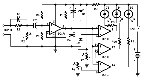 |
| 2W, 12.5W, 24.5W - Three Level Audio Power Indicator Circuit Diagram |
Parts:
- R1 100K 1/4W Resistor
- R2 50K 1/2W Trimmer Cermet
- R3 330K 1/4W Resistor
- R4 1M2 1/4W Resistor
- R5 470K 1/4W Resistor
- R6,R7 500K 1/2W Trimmers Cermet
- R8 1K5 1/4W Resistor
- R9-R11 470R 1/4W Resistors
- C1 47pF 63V Ceramic Capacitor
- C2 100nF 63V Polyester Capacitor
- C3 47µF 25V Electrolytic Capacitor
- C4 1µF 25V Electrolytic Capacitor
- D1 BZX79C5V1 5.1V 500mW Zener Diode
- D2 1N4148 75V 150mA Diode
- D3-D5 3mm. Yellow LEDs
- IC1 LM339 Quad Voltage Comparator IC
- SW1 SPST Slider Switch
- B1 9V PP3
- Clip for 9V PP3 Battery
Notes:
- The simplest way to connect this circuit to the amplifier output is to use a twisted pair cable terminated with two insulated crocodile clips.
- Setup is best accomplished with an oscilloscope or an audio millivoltmeter like the one described in these pages.
- A 1KHz sine wave generator with variable output is also required (see a suitable circuit in this website also).
- Connect the generator to the amplifier input and the Audio Power Indicator to the output of the amplifier, in parallel with the oscilloscope probe or the audio millivoltmeter input.
- When using high power outputs disconnect the loudspeakers to avoid Tweeters damage and connect in their place an 8 Ohm 20-30 Watt wirewound resistor.
- Remember that VRMS output is equal to output Peak-to-Peak Voltage divided by 2.828.
- RMS power output in Watts is equal to VRMS2 divided by speaker impedance (usually 8 or 4 Ohms).
- Example: set the output of the 1KHz sinewave generator to read 14V on the audio millivoltmeter (24.5W 8 Ohms). Set R2 until D3 illuminates, and be sure that D3 turns-off when diminishing a little the generators output.
- Do the same with R7 for D4 and R6 for D5. The readings of the audio millivoltmeter must be 10V (12.5W 8 Ohms) and 4V (2W 8 Ohms) respectively.
Subscribe to:
Posts (Atom)
