Showing posts with label charger. Show all posts

Thursday, November 20, 2014

Ultra Fast Battery charger circuit

Ultra Fast Battery Chager for Nickel-Cadmium battery cells [NiCad] which will be discussed in this article is Fast NiCad Battery Charger, called the Ultra Fast Charger Battery Charger NiCad because it can make filling fast NiCad Batteries Cell. A battery charger in Desai has a fast charging capabilities such as Ultra Fast Battery Chager for Nickel-Cadmium battery cells [NiCad] on this article shall be equipped with some ability to protect the battery and charger circuit itself.

Feature owned by Ultra Fast Battery Chager for Nickel-Cadmium battery cells [NiCad] 

  • Autoshut-off, is the ability of the charger to stop charging current to a NiCad battery if the capacity NiCad battery is fully charged.
  • Polarity Protection, with the existence of this capability so if there are mounting the battery on the charger upside yan can be known.
  • Constant output voltage
  • Output currents enough to fill some NiCad batteries at once in parallel.
  • Short Circuit Protection, with the existence of this protection circuit so if there is short-circuit caused by a battery and a charger circuit itself will not damage the other parts are not damaged.
  • Series Ultra Fast Battery Chager for Nickel-Cadmium battery cells [NiCad]


Image series above is a series of schematic drawings for Ultra Fast Battery Chager for Nickel-Cadmium battery cells [NiCad]. Ultra Fast Battery Chager for Nickel-Cadmium battery cells [NiCad] can be used for 8 to 10 NiCad batteries at once with 12 volt output voltage and max current is 3.5 A. The main components in the circuit of Ultra Fast Battery Chager for Nickel-Cadmium battery cells [NiCad] is UC3843 and MC34181. UC3843 chip is a voltage regulator and M34181 is a JFET OpAmp with characteristic low offset voltage, input impedance is very high. MC34181 serves as a voltage comparator.
Here continue read..

Friday, October 17, 2014

12V Powered 12V Lead Acid Battery Charger with Indicator

Some of you might wonder why a charger is needed at all, to charge a 12 Volt battery from a 12 Volt source! Well, firstly the "12 Volt" source will typically vary anywhere from 11 Volt to 15 Volt, and then a battery needs a controlled charge current and voltage, which cannot result from connecting it directly to a voltage source. The charger described here is intended for charging small 12 Volt lead acid batteries, such as the gelled or AGM batteries of capacities between about 2 and 10 Ah, using a cars electrical system as power source, regardless of whether the car engine is running or not. I built this charger many years ago, I think I was still in school back then. On request of a reader of my web site, Im publishing it now, despite being a rather crude circuit.

12V
It works, it is uncritical to build, and uses only easy-to-find parts, so it has something in its favor. The downside is mainly the low efficiency: This charger wastes about as much power as it puts into the battery. The charger consists of two stages: The first is a capacitive voltage doubler, which uses a 555 timer IC driving a pair of transistors connected as emitter followers, which in turn drive the voltage doubler proper. The doubler has power resistors built in, which limit the charging current. The second stage is a voltage regulator, using a 7815 regulator IC. Its output is applied to the battery via a diode, which prevents reverse current and also lowers the voltage a bit.

12V
The resulting charge voltage is about 14.4V, which is fine for charging a gelled or AGM battery to full charge, but is too high as a trickle charger, so dont leave this charger permanently connected to a battery. If you would like to do just that, then add a second diode in series with D3! There is a LED connected as a charge indicator. It will light when the charge current is higher than about 150mA. The maximum charge current will be roughly 400mA. There is an auxiliary output, that provides about 20V at no load (depending on input voltage), and comes down as the load increases. I included this for charging 12V, 4Ah NiCd packs, which require just a limited current but not a limited voltage for charging.

12V
Note that if the charge output is short-circuited, the overcurrent protection of U2 will kick in, but the current is still high enough to damage the diodes, if it lasts. So, dont short the output! If instead you short the auxiliary output, the fuse should blow. I built this charger into a little homemade aluminum sheet enclosure, using dead-bug construction style. Not very tidy, but it works. Note the long leads on the power resistors. They are necessary, because with shorter leads the resistors will unsolder themselves, as they get pretty hot! The transistors and the regulator IC are bolted to the case, which serves as heat sink. The transistors dont heat up very much, but the IC does.
Here continue read..

Friday, September 19, 2014

12V Powered 12V Lead Acid Battery Charger with Indicator

Some of you might wonder why a charger is needed at all, to charge a 12 Volt battery from a 12 Volt source! Well, firstly the "12 Volt" source will typically vary anywhere from 11 Volt to 15 Volt, and then a battery needs a controlled charge current and voltage, which cannot result from connecting it directly to a voltage source. The charger described here is intended for charging small 12 Volt lead acid batteries, such as the gelled or AGM batteries of capacities between about 2 and 10 Ah, using a cars electrical system as power source, regardless of whether the car engine is running or not. I built this charger many years ago, I think I was still in school back then. On request of a reader of my web site, Im publishing it now, despite being a rather crude schema.

12V
It works, it is uncritical to build, and uses only easy-to-find parts, so it has something in its favor. The downside is mainly the low efficiency: This charger wastes about as much power as it puts into the battery. The charger consists of two stages: The first is a capacitive voltage doubler, which uses a 555 timer IC driving a pair of transistors connected as emitter followers, which in turn drive the voltage doubler proper. The doubler has power resistors built in, which limit the charging current. The second stage is a voltage regulator, using a 7815 regulator IC. Its output is applied to the battery via a diode, which prevents reverse current and also lowers the voltage a bit.

12V
The resulting charge voltage is about 14.4V, which is fine for charging a gelled or AGM battery to full charge, but is too high as a trickle charger, so dont leave this charger permanently connected to a battery. If you would like to do just that, then add a second diode in series with D3! There is a LED connected as a charge indicator. It will light when the charge current is higher than about 150mA. The maximum charge current will be roughly 400mA. There is an auxiliary output, that provides about 20V at no load (depending on input voltage), and comes down as the load increases. I included this for charging 12V, 4Ah NiCd packs, which require just a limited current but not a limited voltage for charging.

12V
Note that if the charge output is short-schemaed, the overcurrent protection of U2 will kick in, but the current is still high enough to damage the diodes, if it lasts. So, dont short the output! If instead you short the auxiliary output, the fuse should blow. I built this charger into a little homemade aluminum sheet enclosure, using dead-bug construction style. Not very tidy, but it works. Note the long leads on the power resistors. They are necessary, because with shorter leads the resistors will unsolder themselves, as they get pretty hot! The transistors and the regulator IC are bolted to the case, which serves as heat sink. The transistors dont heat up very much, but the IC does.

Source: Homo Ludens
Here continue read..

Thursday, September 11, 2014

Simple accu charger circuit

charger
Accu charger circuit is very simple and easy to make, because it only requires a few components are also not more than 10 components. Besides easy charger circuit is also very cheap and very efficient. 


This circuit requires power supply from a transformer that comes from an AC voltage 220 ​​and diuturunkan be 12-13 volts and then enter to-circuit and 12 Volt DC output allows for charging 12V ​​battery

charger
Simple charger schematics
Here continue read..

Tuesday, December 24, 2013

Build A Homemade Fence Charger Energizer Circuit Explained

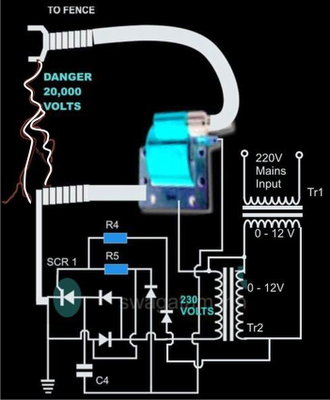
The electric fence charger circuit presented here is basically a high voltage pulse generator. The super high voltage is derived from a commonly used automobile ignition coil. An a stable multivibrator is used to generate the required frequency to drive the ignition coil. Another a stable is used to control the pulses supplied to the fence.

 If you have large agricultural fields and desperately need to protect the crops from uninvited guests like animals and possibly humans, then this electric fence charger device is just what you are looking for. Build and install it yourself. An electric fence is an electrified high voltage barrier which produces painful shocks if physically touched or manipulated. Thus such fencing basically function as deterrents for animals as well as human intruders and stop them from crossing the restricted boundary.

Build  A Homemade Fence Charger Energizer Circuit Explained

Build  A Homemade Fence Charger Energizer Circuit Explained


The present circuit of an electric fence charger is designed and tested by me and has proved sufficiently powerful for the application. The circuit is able to produce voltage pulses up to 20,000 volts, needless to say about the fatality rate involved with it. However the pulses being intermittent, provides the subject with enough time to realize, recover and eject.

The generated pulse is so powerful that it can easily arc and fly-off between short distances of around a cm. so the fencing conductor needs to be separated adequately to avoid leakages through arcing and sparking. If not tackled, may drastically reduce the effectiveness of the unit.

Here the generation of high voltage is primarily carried out by an automobile ignition coil.

The winding ratios of an ignition coil are specifically designed and intended for creating high voltage arc between a two closely spaced conductors inside the ignition chamber to initiate the ignition process in vehicles.

Basically it’s just a step-up transformer, which is able to step-up an input applied voltage at its primary winding to monstrous levels at its output or the secondary winding.

SOME POINTS OF THE CIRCUIT AND THE IGNITION COIL IS VERY DANGEROUS TO TOUCH WHEN POWERED. ESPECIALLY THE IGNITION COIL OUTPUT IS TOO LETHAL AND MAY EVEN CAUSE PARALYSIS.

Let’s diagnose the whole thing more deeply.

Circuit Description


In the CIRCUIT DIAGRAMwe see that the entire circuit is basically comprised of four stages.

A DC oscillator stage, An intermediate 12 to 230 volts step-up stage, The voltage collector and firing stage and The super high voltage-booster stage.

 TR1 and TR2 are two normal step-down transformers whose secondary windings are connected through SCR2. TR2’s input primary winding may be selected as per the country specification.

However, TR1’s primary should be rated at 230 volts.

IC1 along with the associated components forms a normal astable multivibrator stage. The supply voltage to the circuit is derived from the secondary of TR2 itself.

The output from the astable is used to trigger SCR2 and the whole system, at a particular fixed intermittent rate as per the settings of P1.

During the ON periods, SCR2 connects the 12 volt AC from TR2 to the secondary of TR1 so that a 230 volt potential instantly becomes available at the other end of TR1.

 This voltage is fed to the voltage-firing stage consisting of the SCR1 as the main active component along with a few diodes, resistor and the capacitor C4.

The fired voltage from SCR1 is dumped into the primary winding of the ignition coil, where it is instantly pulled to a massive 20,000 volts at its secondary winding. This voltage may be suitably terminated into the fencing.

The high voltage generated by this electric fence charger will need to be carefully applied across the whole length of the fence.

The two poles from the ignition coil connected to the fence wiring should be kept at least 2 inches apart.

 The pillars of the fence should be ideally made of plastic or similar non conducting material, never use metal and not even wood (wood tend to absorb moisture and may give path to leakages).

 Parts List

R4 = 1K, 1WATT,
R5 = 100 OHMS, 1WATT,
P1 = 27K PRESET
C4 = 105/400V PPC,
ALL DIODES ARE 1N4007,
IC = 555
TR1 = 0-12V/3Amp (120 or 230V)
TR2 = 0-12V/1Amp (120 or 230V)
BOTH THE SCRs ARE C106 OR PREFERABLY BT151,

TWO WHEELER IGNITION COIL IS SHOWN IN FLUORESCENT BLUE COLOR

Here continue read..