Tuesday, November 18, 2014
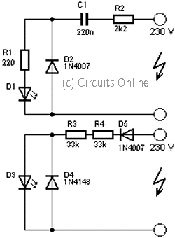
230Volt LED Circuit

Tuesday, November 11, 2014
Mains Powered White LED Lamp
 Did it ever occur to you that an array of white LEDs can be used as a small lamp for the living room? If not, read on. LED lamps are available ready-made, look exactly the same as standard halogen lamps and can be fitted in a standard 230-V light fitting. We opened one, and as expected, a capacitor has been used to drop the voltage from 230 V to the voltage suitable for the LEDs. This method is cheaper and smaller compared to using a transformer. The lamp uses only 1 watt and therefore also gives off less light than, say, a 20 W halogen lamp. The light is also somewhat bluer. The circuit operates in the following manner: C1 behaves as a voltage dropping ‘resistor’ and ensures that the current is not too high (about 12 mA).
The bridge rectifier turns the AC voltage into a DC voltage. LEDs can only operate from a DC voltage. They will even fail when the negative voltage is greater then 5 V. The electrolytic capacitor has a double function: it ensures that there is sufficient voltage to light the LEDs when the mains voltage is less than the forward voltage of the LEDs and it takes care of the inrush current peak that occurs when the mains is switched on. This current pulse could otherwise damage the LEDs. Then there is the 560-ohm resistor, it ensures that the current through the LED is more constant and therefore the light output is more uniform.
Source link:http://www.extremecircuits.net/2010/07/mains-powered-white-led-lamp.html
Thursday, November 6, 2014
Simple Strip LED Lamp
Simple Strip LED Lamp Circuit diagram:
Saturday, October 18, 2014
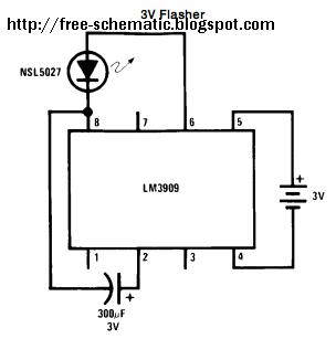
lm3909 led flasher

The LM3909 is a monolithic oscillator specifically designedto flash Light Emitting Diodes By using the timing capacitor
for voltage boost it delivers pulses of 2 or more volts to the LED while operating on a supply of 1 5V or less The circuit is inherently self-starting and requires addition of only a battery and capacitor to function as an LED flasher
Packaged in an 8-lead plastic mini-DIP the LM3909 will operate over the extended consumer temperature range of b25 C to a70 C It has been optimized for low power drain and operation from weak batteries so that continuous operation life exceeds that expected from battery rating
Application is made simple by inclusion of internal timing resistors and an internal LED current limit resistor As shown in the first two application circuits the timing resistors supplied are optimized for nominal flashing rates and minimum power drain at 1 5V and 3V
Timing capacitors will generally be of the electrolytic type and a small 3V rated part will be suitable for any LED flasher
using a supply up to 6V However when picking flash rates it should be remembered that some electrolytics have very broad capacitance tolerances for example b20% to a100%

Features
Y Operation over one year from one C size flashlight cell
Y Bright high current LED pulse
Y Minimum external parts
Y Low cost
Y Low voltage operation from just over 1V to 5V
Y Low current drain averages under 0 5 mA during
battery life
Y Powerful as an oscillator directly drives an 8X speaker
Y Wide temperature range
Applications
Y Finding flashlights in the dark or locating boat mooring
floats
Y Sales and advertising gimmicks
Y Emergency locators for instance on fire extinguishers
Y Toys and novelties
Y Electronic applications such as trigger and sawtooth
generators
Y Siren for toy fire engine (combined oscillator speaker driver)
Y Warning indicators powered by 1 4V to 200V
Friday, October 10, 2014
Blown Fuse indicator LED Display
A Fuse be the equipment protects that use often most. Because of cheapness can use protect electronics expensive circuit. Generally when fuse torn us can know immediately. but in sometimes Fuse torn already we don’t know. such as in electricity automobile system brake system , the system delays the electric current very much, etc. Fuse torn get into trouble at we must know for immediately the safety. I then beg for to advise the circuit is simple. It is can show with , LED that now. Fuse torn already please. See the illustration by equipment value that show that note for Voltage Source 12V , but if friends want to apply to the level Volt the other. As a result change value R1 and R2 get by can calculate from R1 = (Vin – 2) x 50 and R2 = (Vin – 2) x 10000/2 .
Friday, October 3, 2014
Simple LED Flasher Circuit Using 555 IC
Principle work of this circuit is capacitor C2 charges exponentially through resistors R1, R2 and the resistance of the variable resistor. When C2 has charged to about 2/3 VCC it stops charging and it discharges to about 1/3 VCC through R2 and the VR resistance via pin 7. This is the standard operation of a 555 timer. When a Vcc of 5 V to 15 V DC is applied to the circuit, the LED will start to flash. The frequency of the flashing can be changed by varying the resistance of the potentiometer.
Friday, September 19, 2014
Multi Color LED
How many different conditions do you reckon may be signalled with just one LED? Two, maybe three? Using this simple circuit, a lot more! Admittedly, a two-colour LED is used here. Such a device consists of two light-emitting chips, usually red and green, encapsulated in the same case. It has three pins: two for the anodes, and one for the common cathode. In this way, each diode can be activated separately. Various mixed colours may be obtained by varying the current through the two diodes. At least four discrete colours are then easily perceived: pure red, pure green, orange (I R ≈ 2 I G ) and yellow (I G ≈ 2I R ).
In the present circuit, the LED elements are driven by CMOS three-state buffers type 4503, which, unlike most CMOS ICs from the 4000 series, are capable of supplying up to 10 mA of output current. The LED cur-rents are limited by resistors R1 through R6, whose values invite experiments with brightness and colours according to your own taste.
Circuit diagram :

Multi-Color LED Circuit Diagram
The circuit was originally developed to indicate the state of three inputs, a, b, and c (non-binary, i. e., only one of these is at 1 at any time), with the coniguration (a=b=c=0) representing the fourth state. The latter is decoded by NAND gate IC1. An additional effect is produced by gates IC1a and IC1b, which are connected up into an oscillator circuit producing approximately two pulses per second. These pulses are used to control the common-enable input, DA (pin 1) of the 4503, so as to produce a flickering effect. The oscillator is controlled by means of inputs ‘d’ and ‘e’. Pulling both of these logic high disables the oscillator and the LED driver. With e=0 and d=1 the outputs of the 4503 are switched to three-state, and the circuit is in power-down standby mode.
Although designed for a 12-V supply voltage, the circuit will happily work at any supply volt-age between 5 V and 16 V. Non-used inputs of CMOS ICs must, of course, be tied to ground via 10-100 k W resistors.
Friday, August 29, 2014
Single Cell LED Flashlight
It follows that LEDs are almost ideal for very tiny, low power flashlights, in the less-than-one-watt category. But such a low power flashlight makes sense only if the whole flashlight is small and lightweight, and has a reasonable battery lifetime. But white LEDs require about 3.3 volts each, and typically some extra voltage is needed to provide room for current regulation! Thats why most commercial LED flashlights use at least three alkaline or NiMH cells, or a lithium cell. And often they cant use their batteries all the way down to the true end of their charges!
Using three AA cells isnt really practical for a small flashlight, simply because it will no longer be small! Lithium cells are expensive. So some manufacturers use three button cells, but these last only for minutes and are also expensive compared to their tiny energy contents! So I set out to build a schema that lights a string of white LEDs, using a single alkaline or NiMH cell. That allows using the widely available and inexpensive AA cell, obtaining a small size, low cost and good runtime.
A typical white LED has its best power-efficiency combination at about 20mA, and needs about 3.3V. This makes for a power of about 66mW per LED. I decided to use seven LEDs, because they can be arranged in a nice and compact way with one in the middle and the other six around, and the whole array runs at close to one half watt, which is a reasonable power for a tiny pocket flashlight. To avoid having to control the current separately for each LED, the LEDs were arranged in series. So, I needed a driver schema that will provide about 23V at 20mA, when fed from a 1.2V NiMH rechargeable cell or from a 1.5V alkaline cell. It should be ultra simple, low cost, efficient and reliable. And here it is!
The schema is a self-oscillating boost converter, and I certainly cannot claim having invented it. It is ages old! I only did the detail design of this one, and optimized it in the course of one afternoon. It runs with a beautifully clean waveform, with all components except the LEDs staying completely cold to the touch. At this low power level, even that doesnt guarantee a good efficiency, but I measured it at about 72%, which is quite good for a schema operating from such a low voltage!
How it works:
When switching it on, R1 and D1 bias the transistor into the linear range, through the feedback winding on T1. That causes a current through the 18 turn winding, and thanks to the positive feedback the transistor is driven into saturation. At this moment there will be a base current defined like this: The 1.2V of the cell, plus the 0.2V induced in the feedback winding, minus the 0.7V base-emitter drop of the transistor, make a total of 0.7V, which applied to the 22 ohm resistor gives about 32mA base current. D1 is not conducting a significant current at this time, because the transistor clamps the base voltage to 0.7V and the 3 turn winding subtracts 0.2V from this, so that we end up with only 0.5V across the diode.
This base current keeps the transistor in saturation until its collector current reaches approximately 1A, while the transformer loads up. At this point the transistor will start getting out of saturation, which makes the feedback voltage drop. This very quickly puts the transistor into blockage. The collector voltage will soar as T1 forces current to keep flowing, until D2 starts conducting and discharges the transformer into C2, by means of a quite narrow pulse. During operation this pulse is about 24V high, so that the feedback winding develops -4V, which results in applying about -3.3V to Q1s base, enough to switch it off very fast, but not enough to make the base reverse-conduct.
As soon as the transformer has fully discharged into C2, the voltage on it breaks down, and the transistor enters conduction to start a new cycle. The oscillating frequency is 30kHz, and the transformer operates at a peak flux density of 0.1 tesla, far away from saturation, and low enough to have very low loss. C2 has to eat the load pulses that start at about 1A, and has to keep the voltage constant enough to feed the LEDs an almost smooth DC. The value given works well. If anyone wants to build this schema to run 24 hours a day for 30 years, it would be good to pick a capacitor rated for low ESR and a relatively high ripple current, but for flashlight use a plain standard 47µF, 35V electrolytic capacitor works great.
C1 is not strictly necessary. With a good NiMH cell, the schema works the same without it, so you can save a few cents here. But with the capacitor in place, the schema keeps working better when the cell is almost fully discharged and its internal resistance gets higher, so its better to include it.
Components:
Of course, the part over which most builders will stumble is the transformer. I used an Amidon EA-77-188 core, because I had it at hand, and it was the smallest core I had. I should say that this core is still at least five times larger than required! So feel free to use the smallest ferrite double-E core you can find, or any other ferrite core that offers a closed loop and the possibility of assembling it with an air gap. But then you will have to redo the math!
The main winding has 18 turns, and I wound it with 7 strands of #30 enameled wire twisted together, simply because there is room enough to do so. But this thick wire bundle is huge overkill, like the whole transformer is! The feedback winding was wound with a single strand of that same #30 wire, and it has just three turns. The phasing is like shown in the diagram, of course. If you get the phasing wrong, the schema wont work and the transistor will get warm.
I used masking tape to hold the windings in place on the bobbin. No special insulation is required, because the voltages are so low that the enamel on the wire is insulation enough.
Now comes a very important step: This transformer is airgapped. The two core halves need to be separated by a distance of 0.1mm. I simply stuck little pieces of masking tape on the three legs of one core half, taking advantage of the fact that my masking tape is just the right thickness! Then I assembled the core, wrapping masking tape around it to hold it together.
If you have to use a different ferrite core, you can use my transformers and coils article to learn how to design your transformer. The turns ratio will of course remain 6:1, but the absolute number of turns will change in inverse proportion to the cores cross section. You can look up the data of my core on Amidons or Bytemarks websites, compare that to the data for your core, and go from there. After calculating the turns numbers, you have to calculate the required air gap to obtain an inductance of the main winding of about 40µH.
The transistor I used, the 2SC1226A, is a pretty old part and may no longer be available. I have a bunch of them, so I used it. It has a soft, thin copper tab which can easily be cut off, which is an advantage in this schema, because it allows saving some space! The transistor works cold, so it doesnt really need the tab! If you have to use another transistor instead, feel free, but look for one which has the proper characteristics: It should have a breakdown voltage of about 40V, a maximum continuous current of about 3A, be reasonably fast (mine is very fast, having an Ft of 150MHz!), it should have good saturation characteristics, and it should have a reasonably high hfe (at least 30, ideally about 100) at a current of 1A.
Any different transistor will most likely require a change in the value of R1, to set the proper power level for the LEDs. You can experimentally determine that resistor value, by placing a milliamperemeter in series with the LED string, and selecting the resistor for 20mA in the LEDs. By the way, if you want to build this schema for an alkaline cell instead of a NiMH cell, the resistor should be a bit higher. D2 is a Schottky rectifier. A non-Schottky ultrafast diode could be used too, but the Schottky is better. D1 instead is any plain simple silicon diode.
If your power switch doesnt have very low resistance, it might cause a significant loss in this low voltage schema! If that happens, you could instead place the power switch in series with R1, leaving the rest of the schema permanently energized. That will cost almost no lost battery power, because the only current drain when off will be the leakage through the parts, which should be in the microampere range. But if you place the switch at R1, you should also place a 1 megaohm resistor (or almost any other high value) in parallel with D1, to make sure that the transistor really does stay fully off when it should!
Wednesday, December 25, 2013
Automobile White LED Light
Auto White LED Circuit Schematic

In the Automobile White LED Light circuit, fixed voltage regulator IC1 (7805) provides a steady voltage of 5V across C2. Resistors R1 limits the current flow through the white LED D1 (3v6/350mA) with the help of transistor T1 (and T2), ie components R1, T1 (and T2) provide a constant current to D1. Use a good heat sink for T1. This LED unit gives a constant light output for input voltages ranging from 8 to 18 volts!
Monday, December 23, 2013
Multi Color LED
How many different conditions do you reckon may be signalled with just one LED? Two, maybe three? Using this simple circuit, a lot more! Admittedly, a two-colour LED is used here. Such a device consists of two light-emitting chips, usually red and green, encapsulated in the same case. It has three pins: two for the anodes, and one for the common cathode. In this way, each diode can be activated separately. Various mixed colours may be obtained by varying the current through the two diodes. At least four discrete colours are then easily perceived: pure red, pure green, orange (I R ≈ 2 I G ) and yellow (I G ≈ 2I R ).
In the present circuit, the LED elements are driven by CMOS three-state buffers type 4503, which, unlike most CMOS ICs from the 4000 series, are capable of supplying up to 10 mA of output current. The LED cur-rents are limited by resistors R1 through R6, whose values invite experiments with brightness and colours according to your own taste.
Circuit diagram :
Multi-Color LED Circuit Diagram
The circuit was originally developed to indicate the state of three inputs, a, b, and c (non-binary, i. e., only one of these is at 1 at any time), with the coniguration (a=b=c=0) representing the fourth state. The latter is decoded by NAND gate IC1. An additional effect is produced by gates IC1a and IC1b, which are connected up into an oscillator circuit producing approximately two pulses per second. These pulses are used to control the common-enable input, DA (pin 1) of the 4503, so as to produce a flickering effect. The oscillator is controlled by means of inputs ‘d’ and ‘e’. Pulling both of these logic high disables the oscillator and the LED driver. With e=0 and d=1 the outputs of the 4503 are switched to three-state, and the circuit is in power-down standby mode.
Although designed for a 12-V supply voltage, the circuit will happily work at any supply volt-age between 5 V and 16 V. Non-used inputs of CMOS ICs must, of course, be tied to ground via 10-100 k W resistors.
