Tuesday, October 28, 2014
TA8122 bassed AM FM radio receiver Diagram
A very simple low power AM FM radio receiver electronic projects can be designed using the TA8122 integrated AM FM receiver , manufactured by Toshiba Semiconductor . This radio receiver circuit can be used for portable radio applications or other similar devices .
TA8122 radio receiver circuit supports a wide input voltage range from 1.7 volt up to 7 volts , but for this AM FM radio receiver circuit we will need just a 3 volt DC input voltage ( you can use two 1.5 volt Batteries ) .
Using this receiver integrated circuit you can design a very simple AM FM radio receiver or a radio receiver circuit that supports just one of this band (AM or FM) using few additional components .

Tuesday, September 23, 2014
Stereophonic Radio Receiver TDA7088T
Making an introduction to this part, a operating principle of the stereophonic radio receiver shall be considered, its block diagram shown on pic.4.18. Comparing this diagram with the one of the monophonic receiver given on pic.4.6, one may notice that they are identical, up to the block called "The Decoder". It means that, as already described, exiting the FM detector the LF signal is obtained, i.e. the information that was used to perform the frequency modulation in the transmitter. However, this is not an ordinary LF signal, but the one, called the "composed" (KS) or "multiplexed" (Mpx) signal. Besides the full-scale LF signal used by the monophonic receiver, it also contains the so-called auxiliary signal which allows the separation of left (L) and right (R) channels in the stereophonic receiver. E.g. if a direct broadcast of some band music is performed, the left part of performers is being recorded with one microphone (the signal marked as L), whilst the right side is recorded with the other one (it’s a R signal). These two signals are being led in the FM transmitter in the stage called “the coder”. Exiting the coder we have the multiplexed signal Mpx which contains, in an indirect manner, both left (L) and right (R) signal. Frequency modulation of the transmitter is being performed with the Mpx signal. In the receiver, Mpx signal is obtained on the output of the FM Detector and is then led to the decoder. This stage plays a role complementary to the one of the coder in the transmitter, therefore two signals are exiting it, the L and D signal. They are being amplified over two identical audio amplifiers, then reproduced over two same loudspeakers. The listener can now hear the left half of the performers from the loudspeaker placed on its left, and the right half from the loudspeaker that is placed on its right. The performers that are situated in the middle of the orchestra are being equally reproduced from both loudspeakers, making an impression to the listener as if there’s a third loudspeaker, located in the middle, between the left and right one. Based on all this, the listener has a picture about the layout of the performers in space, which significantly improves the total musical impression.
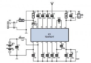
Electronic circuit of a portable stereophonic radio receiver with headphones reproduction, made with TDA7088T is shown on pic.4.19. It is a receiver whose practical realization was described in the previous project, with decoder with TDA7040T and dual audio amplifier with TDA7050T blocks added, the latter was discussed in PE5.
* L3, L4 and L5 are HF chokes that allow for the headphones cable to be used as a reception antenna. This is accomplished by connecting one of the headphones’ contacts from the plug-in, over the 10 pF capacitor, to the point where, acc. to pic.4.14, the outside antenna is connected. The coils represent big resistance to the station signals, preventing them to “go to ground” over the 47 mF capacitor or over the TDA7050T output. Each coil has 3 quirks of the 0.2 mm CuL wire, threaded through ferrite pearls, as shown on detail in the right corner of the pic.4.19. If telescopic antenna is to be used, these coils should be omitted.
Monday, September 22, 2014
VHF FM Receiver TDA7000 88 108 MHz
VHF FM Receiver TDA7000 88 108 MHz
 Here is a very simple VHF FM receiver which is little more than a single IC and a "slack handfull" of capacitors. Note that an external amplifier is a really necessity since the unit only delivers about 70mV of AF.
See High Power FM Wireless Microphone transmitters, probably because it is so simple too.

The 10K resistor (*) is only required if you want the receiver to mute (squelch) under no-signal conditions. You could add a 100K in series with this resistor to get an adjustable squelch. This circuit will JUST drive a crystal earphone or high impedance headphones directly, but an output isolating capacitor (100nF) is needed for any other device. L1 is 6 turns No 18 SWG enamelled wire on a 5mm former, but you may have to play with the values a bit. I used a coil fabricated on the PCB itself, tuned with a trimmer capacitor.

All the other components are just a bunch of capacitors which are fitted to the board at the other side of the chip, just to make it look a bit prettier.

As you can see, this receiver is VERY sensitive, small and seems to work very well indeed. It is in fact a full superhet receiver with a very low RC tuned IF. The Image signal is rejected by the action of the AFC which functions to push it away. With suitable antennas and terrain, with this receiver you could easily get the full 500 meters from the FM wireless microphone v5. I am offering this receiver in kit form, including solder, antenna wire etc. All you will need to provide is the battery, tools and soldering iron. Here is the kit version fully assembled.


The total size is 45mm x 48mm. If there is any interest in the kit then I may even add an AF amplifier kit so that you can make a full bedside/table radio.
Source: TDA7000 RX
