Showing posts with label wireless. Show all posts
Showing posts with label wireless. Show all posts
Friday, June 6, 2014
Arduino Based Low Power Wireless Solution
panStamp is an open source project created for the enthusiasts that love measuring and controlling things wirelessly. panStamps are small wireless boards specially designed to fit in low-power applications, simple to program and simple to work with. With panStamps, you can measure almost everything by simply connecting your panStamp to the sensors, placing a battery and sending wireless data from the first moment.

panStamps are suitable for any kind of project needing remote control and low-power wireless transmissions, including home automation, energy metering, weather monitoring and robot control. If you are one of these three things: a hobbyist, a professional or an end-user, you will find that panStamps provide extreme flexibility and power when creating custom wireless networks. [Link]

Simple Wireless TRIAC Dimmer
This project was used as a wireless light dimmer, but in principle can be used to dim resistive loads and wirelessly turn on/off loads. The current code includes a routine to dim a light bulb in a “heartbeat” pattern, with the heartbeat frequency remotely adjustable.

The top left of the schematic shows the wall outlet (US 120VAC) being stepped down with a small transformer, then full rectified and regulated. This powers the entire board from the wall. The top right shows a microcontroller, ATmega48, its programming header, and a UART connection to the microcontroller (for debugging). The bottom right shows the XBee and its basic voltage regulation (it’s 3.3V), as well as an LED that indicates when the XBee is connected. [Link]
Wireless Stepper Motor Controllers Circuit Diagram
Here is a low-cost and simple wireless stepper motor controller using infrared signals. Using this circuit you can control the stepper motor from a distance of up to four meters.
The circuit comprises transmitter and receiver sections. The communication between the transmitter and receiver sections is achieved through infrared signals.
The circuit comprises transmitter and receiver sections. The communication between the transmitter and receiver sections is achieved through infrared signals.
Wireless Stepper Motor Controllers Circuit Diagram

In the transmitter section, timer NE555 ICs (IC1 and IC2) are configured as astable multivibrators with frequencies of around 1 Hz and 38 kHz, respectively. The output of IC1 is given to reset pin 4 of IC2, so the 38kHz carrier signal is modulated by 1Hz modulating signal. The modulated signal from pin 3 of IC2 is transmitted by the infrared LED. Resistor R5 limits the current through the IR LED.
The transmitted signal is sensed by IR receiver module TSOP1738 (IC6) of the receiver section and its output at pin 3 is used as clocks for dual flip-flop 74LS74 Ics (IC3 and IC4), which are configured as a ring counter.
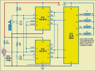
Fig. 2: Infrared receiver and stepper motor driver circuit
The outputs of flip-flops are amplified by the Darlington transistor array inside ULN2003 (IC5) and connected to the stepper motor windings marked ‘A’ through ‘D.’ The common point of the windings is connected to +12V DC supply.
To stop the motor, the flip-flops can be reset manually by pressing reset switch S1. On releasing the reset switch, the stepper motor again starts moving. If any interruption occurs between the transmitter and the receiver, the motor stops
Sourced By EFY Author Jaydip Appasaheb Dhole
Subscribe to:
Posts (Atom)
