Monday, November 17, 2014
DC Motor Speed Control using PWM
Schmitt Trigger function that produces a square wave will become the sawtooth wave or integrator is also called common rail and the ramp compared to a reference voltage that can change a lot of stress. So the result is a PWM output.

Wednesday, November 12, 2014
LM317 based DC motor speed controller with circuit
A very simple DC motor speed controller circuit can be constructed using a LM317 voltage regulator integrated circuit . This DC motor speed controller can be used for speed control of mini drills or for other small DC motors . This motor controller circuit will provide a large output current . The maximum output current from the secondary turns of the transformer shout provide 1.5 times of the maximum DC output current . The output voltage and the speed ( rpm ) is set by the P2 variable resistor .
As soon as the current drawn exceeds a certain value , T2 will be switched on . This results in a base current for T3 so that R5 is in parallel with R6 . This automatically raise the output voltage to counter a threatened drop in rpm . The moment at which this action occurs is set by P1 .
Friday, October 24, 2014
Skema Rangkaian Pengapian Motor CDI

A similar Schmitt trigger oscillator is used to trigger the SCR about 4 times per second. The power supply is gated off during the discharge time so that the SCR will stop conducting and return to its blocking state. The diode connected from the 3904 to pin 9 of the 74C14 causes the power supply oscillator to stop during discharge time. The circuit draws only about 200 milliamps from a 12 volt source and delivers almost twice the normal energy of a conventional ignition circuit.
High voltage from the coil is about 10KV using a 3/8 inch spark gap at normal air temperature and pressure. Spark rate can be increased to possibly 10 Hertz without losing much spark intensity, but is limited by the low frequency power transformer and duty cycle of the oscillator. For faster spark rates, a higher frequency and lower impedance supply would be required. Note that the ignition coil is not grounded and presents a shock hazard on all of its terminals. Use CAUTION when operating the circuit.
An alternate method of connecting the coil is to ground the (-) terminal and relocate the capacitor between the cathode of the rectifier diode and the positive coil terminal. The SCR is then placed between ground and the +340 volt side of the capacitor. This reduces the shock hazard and is the usual configuration in automotive applications.
Sunday, September 21, 2014
Fuse Box Ford 1993 F150 Shift Motor Diagram
Fuse Box Ford 1993 F150 Shift Motor Diagram


Fuse Panel Layout Diagram Parts: electronic clutch feed, transfer case motor control, speed sensor, shift position sensor.
Friday, June 6, 2014
Wireless Stepper Motor Controllers Circuit Diagram
The circuit comprises transmitter and receiver sections. The communication between the transmitter and receiver sections is achieved through infrared signals.
Wireless Stepper Motor Controllers Circuit Diagram

In the transmitter section, timer NE555 ICs (IC1 and IC2) are configured as astable multivibrators with frequencies of around 1 Hz and 38 kHz, respectively. The output of IC1 is given to reset pin 4 of IC2, so the 38kHz carrier signal is modulated by 1Hz modulating signal. The modulated signal from pin 3 of IC2 is transmitted by the infrared LED. Resistor R5 limits the current through the IR LED.
The transmitted signal is sensed by IR receiver module TSOP1738 (IC6) of the receiver section and its output at pin 3 is used as clocks for dual flip-flop 74LS74 Ics (IC3 and IC4), which are configured as a ring counter.
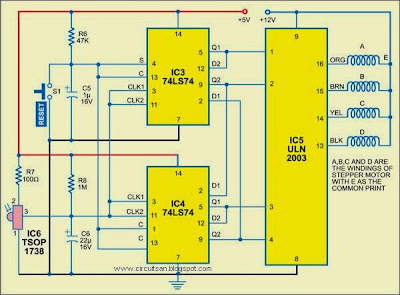
The outputs of flip-flops are amplified by the Darlington transistor array inside ULN2003 (IC5) and connected to the stepper motor windings marked ‘A’ through ‘D.’ The common point of the windings is connected to +12V DC supply.
To stop the motor, the flip-flops can be reset manually by pressing reset switch S1. On releasing the reset switch, the stepper motor again starts moving. If any interruption occurs between the transmitter and the receiver, the motor stops
