Thursday, November 20, 2014
Ultra Fast Battery charger circuit
Ultra Fast Battery Chager for Nickel-Cadmium battery cells [NiCad] which will be discussed in this article is Fast NiCad Battery Charger, called the Ultra Fast Charger Battery Charger NiCad because it can make filling fast NiCad Batteries Cell. A battery charger in Desai has a fast charging capabilities such as Ultra Fast Battery Chager for Nickel-Cadmium battery cells [NiCad] on this article shall be equipped with some ability to protect the battery and charger circuit itself.
Feature owned by Ultra Fast Battery Chager for Nickel-Cadmium battery cells [NiCad]
- Autoshut-off, is the ability of the charger to stop charging current to a NiCad battery if the capacity NiCad battery is fully charged.
- Polarity Protection, with the existence of this capability so if there are mounting the battery on the charger upside yan can be known.
- Constant output voltage
- Output currents enough to fill some NiCad batteries at once in parallel.
- Short Circuit Protection, with the existence of this protection circuit so if there is short-circuit caused by a battery and a charger circuit itself will not damage the other parts are not damaged.
- Series Ultra Fast Battery Chager for Nickel-Cadmium battery cells [NiCad]

Image series above is a series of schematic drawings for Ultra Fast Battery Chager for Nickel-Cadmium battery cells [NiCad]. Ultra Fast Battery Chager for Nickel-Cadmium battery cells [NiCad] can be used for 8 to 10 NiCad batteries at once with 12 volt output voltage and max current is 3.5 A. The main components in the circuit of Ultra Fast Battery Chager for Nickel-Cadmium battery cells [NiCad] is UC3843 and MC34181. UC3843 chip is a voltage regulator and M34181 is a JFET OpAmp with characteristic low offset voltage, input impedance is very high. MC34181 serves as a voltage comparator.
AT89Sxx Base Board
The board is based on the AT89S51, AT89S52, or AT89S53. This board uses STK200 for program loading and includes the serial port at the STK200 header. When I need to program the MCU and need a serial comunication, I do not need to plug and unplug the connector. Because I am using the USB to Serial ISP programmer. Then with the STK200, we must built the parallel programmer STK200. This parallel programmer STK200 can also be use for AVR programmer. This is the reason for the new design.![]()

![]()
Here continue read..
The PCB layout.
Easy Downloader Circuit
Atmel microcontroller series AT89Cxx51 Easy Downloader is one of the downloader that is often used to write data to program the Atmel microcontroller AT89CXX51. Easy Downloader AT89Cxx51 ATMEL microcontroller is using the serial port as a channel of communication with the computer. Easy Downloader ATMEL Microcontroller AT89Cxx51 can be used to program Atmel AT89CXX51 in parallel. Atmel microcontroller series AT89Cxx51 Easy Downloader is quite simple to make your own because the components necessary to membutanya not complex. Atmel microcontroller series AT89Cxx51 Easy Downloader do not support the serial programming microcontrollers ISP. In the article Easy Downloader ATMEL Microcontroller AT89Cxx51 only displays images Easy Downloader Microcontroller series from Atmel AT89Cxx51 mengulasnya only and are simple.

Wednesday, November 19, 2014
144 MHz Simple RF Detector Circuit
This simple circuit helps you sniff out RF radiation from your transmitter, improper joints, a broken wire or poor equipment with RF shielding. The tester is designed for the radio band amateur 2 meter (144-146 MHz in Europe). The instrument has a reading of 4-step LED and an audible alarm for high voltage radiation. The RF signal is received by an antenna and made to resonate by C1-L1. After rectification by the diode D1, the signal is fed to a two transistor Darlington amplifier HighGain, T2-T3. Assuming a 10-inch telescoping antenna using the RF level scale established for the LEDs is as follows:
When all the LEDs light, the (optional) UM66 sound / melody generator chip (IC1) also operates and provides an audible alarm. By changing the zener diode values of D2, D4, D6 and D8, the step size and duration of the instrument may change as needed. To operate in other bands of ham or PMR, simply change the network-L1 C1 resonance.
For example, a transceiver 5 watt handheld equipped with a telescoping half-wave antenna (G = 3.5 dBd), there is an ERP (Effective Radiated Power) of just 10 watts and an emf of more than 8 volts near the head. Inductor L1 consists of 2.5 turns of 20 SWG (approximately 1 mm in diameter) enameled copper wire. The inner diameter is approximately 7 mm and no core is used.
Trimmer capacitor C1 associates is adjusted for the greatest number of LEDs to light at a relatively low fieldstrength position for a 2 m transceiver 145 MHz transmission. The tester is powered by a 9 V battery and consumes about 15 mA when all LEDs are on. Must be enclosed in a metal box.
Preamplifier Microphone with 2 Transistor
Microphone preamplifier or often known as mic preamp can be made use simplemicrophone preamplifier circuit as follows. 2 microphone preamplifier circuit uses 2transistors are PNP and NPN transitor amplifier.
Front of the microphone amplifier orpreamplifier microphone 2 transistor uses a system of dc negative feedback through R6which serves to provide stability strengthening. Level output signal from the microphonepreamplifier is controlled by potentiometer P1. Input signal that can be responded well by this microphone preamplifier is 0.2 - 200mV and 1V RMS output will result.

Microphone preamplifier circuit two transistors in the show above is preampmic suitable for home audio system on the stereo. This microphone preamplifier circuit requires supply voltages 9Vdc.
Front of the microphone amplifier orpreamplifier microphone 2 transistor uses a system of dc negative feedback through R6which serves to provide stability strengthening. Level output signal from the microphonepreamplifier is controlled by potentiometer P1. Input signal that can be responded well by this microphone preamplifier is 0.2 - 200mV and 1V RMS output will result.
Component List P1 2k2
R1, R2, R3 100K 1/4W
R4 8K2 1/4W
R5 68R 1/4W
R6 6K8 1/4W
R7, R8 1K 1/4W
R9 150R 1/4W
C1 1uF 63V
C2, C3, C4 100uF 25V
C5 22uF 25V
Q1 BC560C
Q2 BC550C
R1, R2, R3 100K 1/4W
R4 8K2 1/4W
R5 68R 1/4W
R6 6K8 1/4W
R7, R8 1K 1/4W
R9 150R 1/4W
C1 1uF 63V
C2, C3, C4 100uF 25V
C5 22uF 25V
Q1 BC560C
Q2 BC550C
TA8210AH Stereo Car Power Amplifier
IC TA8210AH By using this you can apply a series of audio power amplifier is the car audio system. In general, all the speakers in the car using a subwoofer speaker, and woofer. Because the car is not big room so the sound is being required is not too high.
Audio amplifier circuit can work at a minimum voltage 12-volt DC, if supplied under voltage 12-volt amplifier work will be less than the maximum. This amplifier output power up to 200W or 2 x 100W stereo with 8 ohm impedance.
Audio amplifier circuit can work at a minimum voltage 12-volt DC, if supplied under voltage 12-volt amplifier work will be less than the maximum. This amplifier output power up to 200W or 2 x 100W stereo with 8 ohm impedance.
Part List :
R1 =1K
R2 =50K trim
R3 =1K
R4 =50K trim
R5 =680R
R6 =680R
R7 =150K
R8 =2R2
R9 =2R2
R10=2R2
R11=2R2
Capacitor
C1 =1uF
C2 =1uF
C3 =47uF
C4 =47uF
C5 =100n/400V
C6 =220uF
C7 =220uF
C8 =100n/400V
C9 =100n/400V
C10=100n/400V
Intregated Circuit
IC1=TA8210AH
Connector
X2-3=in R
X2-2=gnd
X2-1=in L
X1-1,X1-2=Out R
X1-3,X1-4=Out L
Tuesday, November 18, 2014
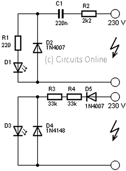
230Volt LED Circuit
This is a circuit that is used to menhidupkan LED with voltage 230Volt, 230Volt it so that the voltage must be lowered in accordance with the needs of the LED itself. To lower it even necessary circuit as below.
Subscribe to:
Posts (Atom)